
API.HCl Salts directly from HCl Gas: Enabling Continuous Multiphase API and HCl Gas Processes with SpinPro.
The production of the HCl salt in API processing does not need to be a stumbling block. It can be done directly and cleanly with dry HCl gas. The salt forms in a controlled way as a solid to be filtered off. Flowid’s SpinPro dynamic reactor technology can handle both the HCl as the generated solids exceptionally well.
Authors: W.J.N. Klement¹, J.Q. Brouwer², J.M.B. Klement², W.R. Browne², K.M.P. van Eeten¹
(1) Flowid
(2) University of Groningen, Faculty of Science and Engineering
Introduction to API salts
HCl salts of pharmaceutical ingredients are commonly prepared to increase their stability and efficacy. A HCl salt is, simply, a compound bound to HCl to form a salt. Examples are Lidocaine, (sold as Lidocaine.HCl) and Epinephrine, which is also sold and used in its HCl salt form. Since the salt form is how the product is used and sold, obtaining the salt is often the final step of a production process before tabletting and packaging.
Chemical Characteristics of API HCl salts
Chemically, a HCl salt is often recognizable as an organic molecule containing a nitrogen somewhere in the structure. A HCl molecule can interact with this nitrogen to form a chloride salt by donating a H+ to the nitrogen, after which the chloride forms the counterion (Cl-). In the chemical structure of Epinephrine, the HCl binds at a methyl amine nitrogen (Figure 1). The nitrogen in pyridine rings, a common substructure in APIs, is also a prime binding site for HCl.
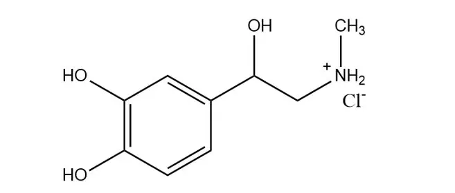
Figure 1: Chemical structure of Epinephrine HCl.
Challenges of producing salts of APIs
Batch production of API hydrochlorides from HCl gas in large vessels requires long residence times, due to the multiphase nature of the process. Batch reactions generate heat and require cooling producing low temperature waste heat. Additionally, the product is often generated as a solid when processing this way, which can lead to clogging and hindered heat transfer. These aspects often force alternative solutions (other chemical pathways) in the manufacturing of hydrochloride salts.
HCl salts can be prepared in a number of ways, ranging from complex methods involving mediation of a silane, to simpler methods which use hydrochloric acid solutions. Using HCl gas directly to form the HCl salt provides an effective route with perfect atom economy and the least waste.
The apparent widespread use of alternative and complex ways to produce this product type should already indicate that their production does not come without challenges. Technical challenges and safety concerns in working with this gas currently limit this approach on larger scales. HCl as a gas is highly reactive, harmful, corrosive, and, since the pharmaceutically active ingredient is converted to a solid, the conversion is a multiphase slurry reaction, which comes with additional challenges in mass and heat transfer.
Continuous manufacturing and process intensification can speed up the reaction in a controlled way, maintaining a constant temperature, enabling work at higher temperatures, higher concentrations, and, using HCl gas directly with highly reduced risk.
Why mixing and heat transfer matters in HCl gas reactions
Separate phases, such as the HCl gas and the liquid solution of an API, by their nature are difficult to mix at the molecular level, which is needed for reactions. Traditional mixing of two phases in a batch vessel or tank provides little interaction due to the lack of phase boundary (the layers formed at the contact between the two phases). Reagents in either phase do not meet and, as a consequence, mass transport limits reactions in multiphase systems much more than in reactions in a single phase with all components miscible. Moreover, the turbulence intensity and level of shear in these systems are relatively low and non-homogeneous, which further reduces mass transfer rates.
Multiphase reactions are therefore often very slow as a result of these factors. Long reaction times reduce efficiency, necessitate long residence times, and the need for large vessels. Given the dangers of HCl gas, scaling up these processes in batch mode becomes challenging and restrictively dangerous to handle. The main challenge is that the liquid and gas phases stay separate, while mixing and thus reactivity is limited to the surface between the phases.
SpinPro: Rotor-Stator Spinning Disc Reactor
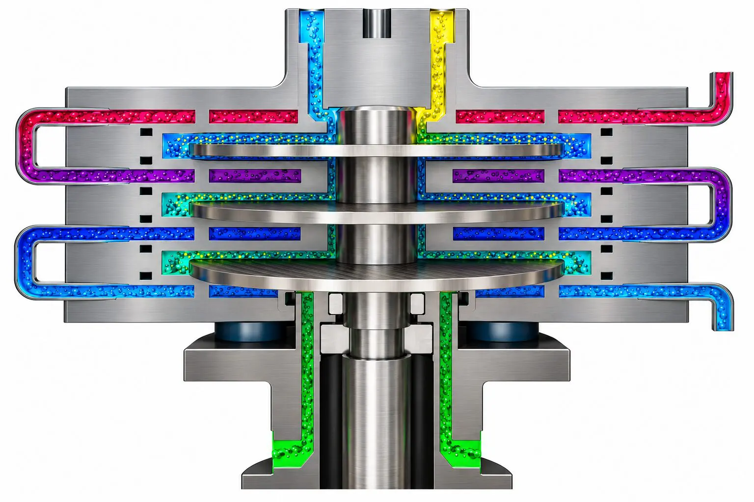
The rotor-stator spinning disc reactor utilizes intense turbulence and high shear in a small cavity, combined with high heat transfer. In short, these aspects provide a highly controlled reactive environment, where mixing and thermal control are maximized. Control over these parameters is applied externally to the reactor by means of the disc rotations within the reactor, and utility flow to the reactor for the temperature. As such, these important processing parameters can be tuned independently of the flowrate, further increasing the control available over the process.
Benefits of Rotor-Stator Spinning Disc Reactors for Multiphase Reactions with HCl
Dynamic processing is a reliable option to effectively scale up multiphase gas/liquid reactions with reactive gasses. High shear causes the liquid and gas phases to mix, which greatly reduces distances reagents have to travel to meet each other, and, therefore greatly increases reaction rates. Without stirring, the two phases pass through in an alternating slug flow fashion (Figure 2) and barely react. With the intense shear, their reaction rates increase drastically.
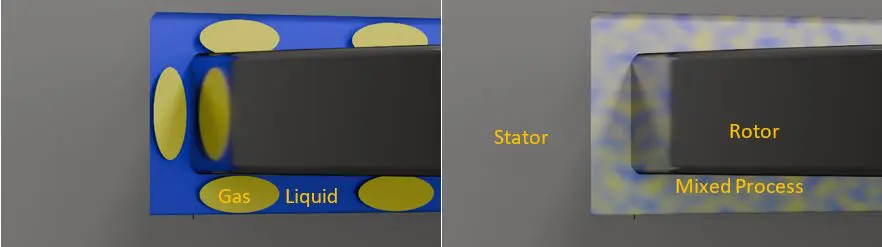
Figure 2: Two phases (yellow and blue) flowing through a SpinPro rotor stator reactor where the rotor is not spinning (left) and when the rotor is spinning (right).
In batch processing, such high rates would cause problems due to limited heat transfer possibilities and inherent inhomogeneities in local high shear mixers in a bigger tank. Though, in flow heat is controlled much more readily and therefore does not pose a large limitation. An additional benefit of the high shear environment is the solid handling. Produced salts are ejected from the reactor without clogs and can be filtered off.
Experimental results and process performance
Hydrochlorination of pyridine was chosen as an example reaction for HCl salt formation, as many active pharmaceutical ingredients (APIs) contain a pyridine heterocycle or amine within their structure. Examples of APIs with a pyridine moiety are omeprazole, esomeprazole, amlodipine, imatinib and atazanavir. In these drugs, the pyridine nitrogen is often the ‘acceptor’ for the HCl, making pyridine an interesting reference. The product pyridine hydrochloride salt, is a solid, and neat production would clog the reactor. Hence, pyridine is mixed with toluene as a carrier liquid (eluent). The mixture is pumped into the SpinPro reactor, using a Tuthill gear pump.
Hydrochloride salts can be prepared using concentrated hydrochloric acid. The aqueous acid is directed into the SpinPro reactor together with the pyridine/toluene mixture. In line Raman spectroscopy shows that there is little conversion without rotation, and high conversion with rotation. In both cases, the exit feed is a bi-phasic liquid, as unreacted excess of pyridine remains in the toluene, whereas the product HCl salt dissolves in the water from the acid stream. The resulting aqueous mixture of product requires energy intensive dehydration to obtain the solid HCl salt from the water-rich stream. This energy intensive step can be avoided by using HCl gas instead.
In our FlowLab, we set up a SpinPro reactor with inlets for the reagents and gas. Additionally, the reactor is outfitted with a thermal probe within the reactor itself, and a Raman probe directly at the outlet of the reactor. HCl is dosed either as the liquid, using a HNP pump, or as gas dosed dry, using a Bronkhorst HCl gas dosing system.
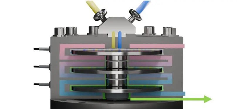
Figure 3: Insides of a SpinPro reactor. Blue and yellow reagents are dispersed by rotation of the central discs. Reaction occurs to form product (green). Utility streams are used to cool the reactor (blue to red).
In-line analysis using Raman spectroscopy
Process optimisation can be accelerated by in line reaction monitoring. While not the topic of the current article, a brief description is given here. Analysis of the process was performed in line, using Raman spectroscopy. The probe is built using a 785 nm laser, for which the used PFA tubing is transparent. As a result, the laser can see contents inside the process stream, offering real-time data.
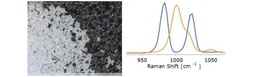
Figure 4: Microscopy image of the microcrystalline product (left), and Raman spectra from inside the process stream (right) showing the product (orange) and starting material (blue). The product has a different fingerprint than the starting material. The product is only observed when rotation is on.
Processing parameters of API HCl produced from HCl gas
Both versions of this experiment, with either the aqueous or gaseous HCl, produced excellent results in terms of yields and residence times. The operating window of the salt production using the gas directly is described here.
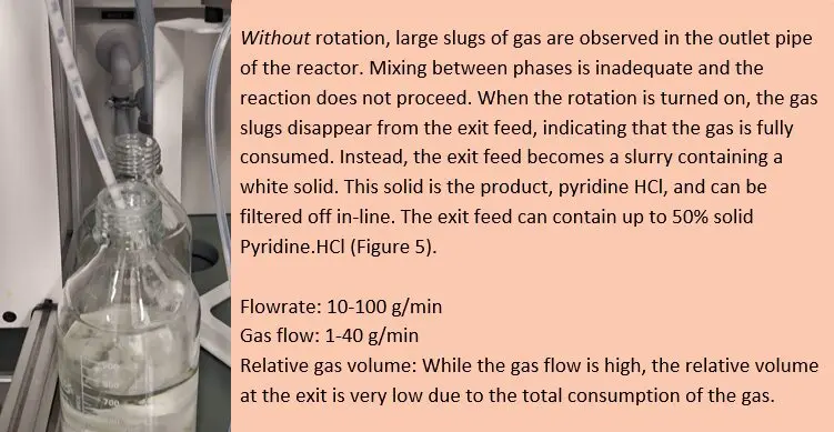
Figure 5: Pyridine HCl salt (white solid) obtained from pyridine using HCl gas, with toluene used as eluent. The reactor exit tube where the solid product can be observed is shown in the picture. HCl gas is fully consumed avoiding release from the outlet.
Conclusion
Pyridine HCl was produced as a solid, white product directly from pyridine and HCl gas using a SpinPro rotor-stator spinning disc reactor. The product could be directly filtered off without further workup. The productivity of the small and easy to handle 19 mL reactor is comparable to a typical batch vessel of 1000 Liter, but poses less operational risks. The outflow of the reactor did not contain any gas (all gas is reacted) and instead is a slurry containing the product and eluent. HCl salts could be obtained using both gaseous HCl and its aqueous solution. Similar high yields and easy processability were found for adenine and ammonia.